Lotus Off-Road Suspension Project

Overview of quarter vehicle model

2D 'skeleton' model used to analyse the system kinematics

Effect of changing the lower spring & damper mounting position on stress concentrations and magnitude

Overview of quarter vehicle model
Lotus Suspension - Design
2016
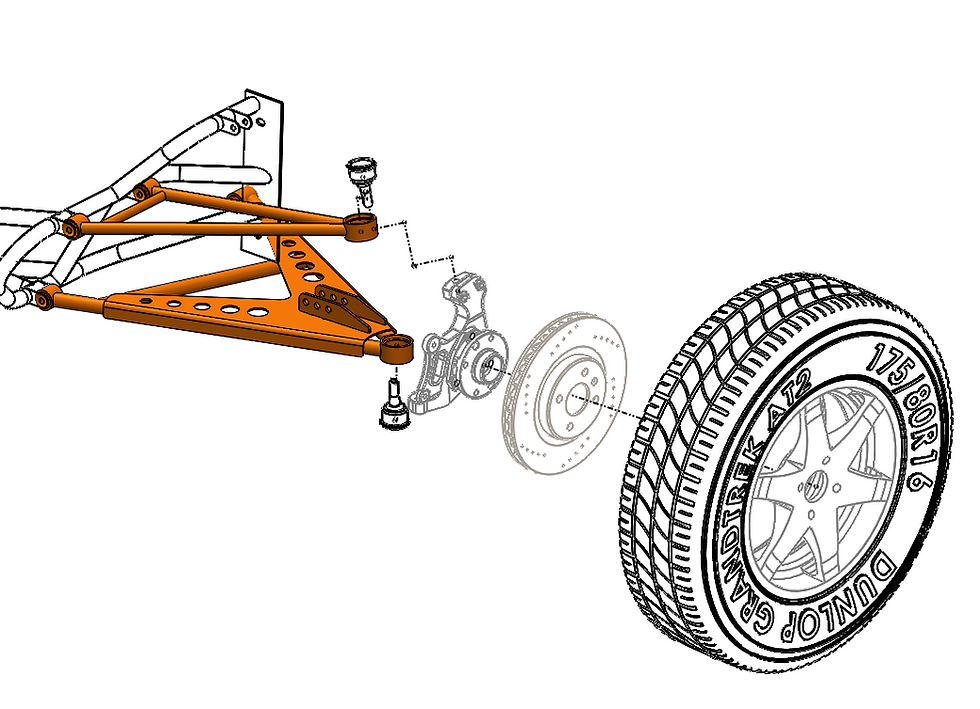
My masters dissertation was titled; "The feasibility of adapting a rear suspension suited for an off-highway application for a Lotus Elise chassis". This involved the full kinematic and dynamic design of the rear suspension to suit Lotus' small vehicle chassis platform. The front suspension was also designed for manufacture although the kinematic design had been previously completed. To do this the the suspension system was designed using preliminary calculations and basic skeleton models to help quantify and assess the performance of various design changes. Kinematic analyses were conducted in Solidworks, the data from these were then fed into MATLAB to create 3D graphs which showed the sensitivity of various design changes, and their effect on system performance. Once this was completed suspension calculations were completed to find the 'ideal' values based on the geometry. These were then reworked with the nearest readily available parts from the manufacturers.
To help further investigate and improve the vehicle dynamics the suspension system was programmed into Dymola, a simulation environment. Due to the complex nature of the triple-rate springs selected, this helped ensure that the values selected would produce the desired vehicle handling behaviour. To do this the vehicle was tested, virtually, on a four post rig and on a virtual handling pad. The next step was to conduct structural analysis on the parts to fetermine their performance and whether they were suitable. To get values for this the forces for several key load cases (such as braking and longitudinal & lateral kerb strikes) were calculated using MATHCAD. These were verified using a vehicle with a similar construction and in a similar test environment. The data from this was processed in MATLAB. Finally a design was created and then simulated using the inbuilt Solidworks FEA add-in. The effect of altering the boundary conditions was investigated and designs iterated to give the best end result.